This blog is dedicated to all details about a static voltage regulator. There are many significant differences between the new-age Static regulator and conventional servo unit. Hence, in this post, we will discuss its working, features, and advantages in detail. These differences concern the construction, operation, reliability, and features of both types of systems. Please note, Static IGBT regulators, do not have any moving parts, unlike servo stabilizers. It achieves voltage regulation with the help of static electronic circuits only. In this discussion, we will also understand its working, price aspect, and major manufacturers.
To better understand the working of these types of voltage regulators, we need to understand their main components.
Components of static voltage regulators.
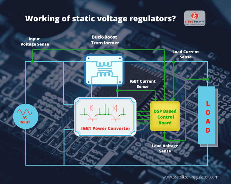
Please refer diagram below. Let’s understand the major components of the Static voltage regulator. Each element has its distinct role, and understanding each part of this machine will certainly help understand its working in detail.

Buck-Boost Transformer.
Secondary winding of Buck and boost transformer is connected input and output terminal of voltage stabilizer. Neutral between input and output of static voltage regulator is common. Hence, the voltage induced across secondary of the buck-boost transformer can add or subtract by changing its input voltage. The primary side of the buck-boost transformer is connected to the IGBT power stage. Thus, if the power stage reduces or increases its output voltages, it will directly affect the secondary of the buck and boost transformer and hence the output of the IGBT voltage regulator.
IGBT Power Stage.
It consists of an IGBT bridge connected to a DSP controller. The IGBT power stage is responsible for generating the appropriate amount of voltage at its output with the help of the PWM method. The output voltage of the IGBT bridge is applied across the primary terminals of the buck-boost transformer. IGBT bridge can generate voltages at its output (which is applied across primary of the buck-boost transformer) which can be in phase or 180 degrees out of phase with input line voltages. Thus, the voltage induced across secondary of the buck-boost transformer can be added to or subtracted from input line voltages of the static voltage regulator.
DSP Control board.
Control board continuously senses values of input voltage, output voltage, load current, and IGBT current with the help of the current transformer (CT) and voltage transformer (VT). It processes information and gives signals to the IGBT power stage to generated voltage using the PWM method.
How static regulator works?
DSP bases control board continuously senses input, output, and IGBT bridge parameters with the help of CTs and VTs. Based on these values DSP control board will trigger the IGBT bridge to generate a voltage at its output. Let’s see in detail the operation of the static regulator in Buck and Boost mode.
Boost mode.
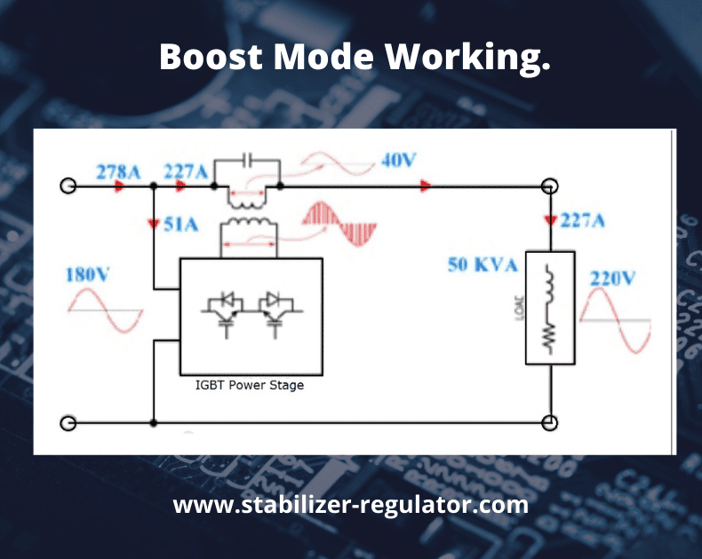
For example, a load of 50kVA, 220V is connected at the output of the static voltage regulator. And suppose a low voltage of 180V is available at the input line, which needs to be corrected to 220V. When the DSP control board senses input & output voltage along with load current and IGBT current, it will trigger the IGBT bridge to generate 40V (220-180=40V) at its output which is in phase with the input line voltages.
transformer. Since both voltages, input line, and the voltage across secondary of the buck-boost transformer are in phase with each other, it gets added, and output voltage corrected to 220v.

Buck mode.
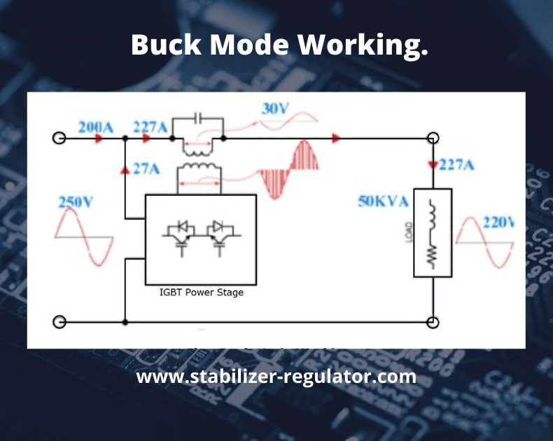
For example, a load of 50kVA, 220V is connected at the output of the static regulator. And suppose a high voltage of 250V is available at the input line, which needs to be corrected to 220V. When the DSP control board senses input & output voltage values and load current and IGBT current to correct voltage, it will trigger the IGBT bridge. IGBT bridger will generate 30V (250-220=30V) at its output 180 degrees out of phase with input line voltages. It induces 30V at secondary of the buck and boost transformer. Since both voltages, the input line and the voltage across secondary of the buck-boost transformer, are 180 degrees out of phase with each other, they get subtracted, and output voltage corrected to 220v. We strongly recommend a static Voltage regulator over a conventional servo voltage stabilizer or servo voltage regulator.

Static voltage regulator vs servo stabilizer.
As we know, there are two main types of working mechanisms, and each has its pros and cons. So let’s figure out the differences between these two types.
Voltage correction speed of static regulator.
The static regulators do not contain any moving parts. The static voltage stabilizer has a pure electronic circuit to achieve correction in voltages. Hence, it has an exceptionally high voltage correction speed than the servo motor unit. The voltage correction speed of the IGBT regulator can be in the range of 360 to 500 V/sec. On the other hand, a servo stabilizer has a moving servo motor with the help of which it achieves correction in voltage. Servo system is an electromechanical device. Thus, its voltage correction speed is slower than the static voltage regulator.
Correction speed.
Due to high voltage correction speed, static units have a low correction time of 20 to 30 milliseconds compared to servo stabilizer correction time of 50 milliseconds to 5 seconds.
Maintenance.
Since the servo stabilizer has a moving servo motor, it has regular wear and tear that needs maintenance. The carbon brush needs replacement after some time. Due to the solid-state design of the electronic units, it hardly needs any care.
Reliability of static voltage regulator.
In servo, motor stabilizer correction in voltage achieves by increasing or decreasing no winding in autotransformer by the shaft of servo motor. It increases or reduces the voltage across the primary of the buck-boost transformer, in turn, secondary of the buck-boost transformer, correcting output voltage. Hence, the reliability of servo-type units mainly depends on the reliability of the servo motor. Similarly, the reliability of static voltage regulators depends on the reliability of the IGBT power stage. In General, the IGBT power stage is more reliable than the electromechanical servo motor. Hence, static regulators are more reliable than a servo.
Auto Bypass facility.
In a static voltage stabilizer providing an auto-bypass is very easy. And due to its fast electronic nature, it is less costly to incorporate bypass in IGBT regulators. Also, it can transfer to bypass automatically and without a break in output voltage (zero transition time) in case of even of fault. It is complicated to provide an auto bypass mechanism in a servo stabilizer, and even if it is facilitated, it will be costly. Also, transition to bypass will be with a break in output voltage (needs transition time).
Protection from overcurrent.
The DSP control board continuously senses various parameters in static voltage regulators as part of its working principle. In the short circuit condition, at the output of the static regulator, load current increases exponentially high, which automatically gets sense by the DSP controller. Thus, it cuts output & switches the IGBT power stage instantaneously to clear overcurrent fault. Hence, over-current faults get addressed in the IGBT stabilizer very quickly and without adding any extra hardware.
In the case of servo voltage stabilizer, over current protection can be achieved with the help of extra hardware (MCCB, CB, etc.), and clearing of fault is not instantaneous.
Other differences.
| Specifications | Static Voltage Regulator | Servo regulator |
|---|---|---|
| RMI/EMI Filter | A standard feature with no extra cost. | Optional feature with extra cost |
| Physical Size | For given KVA it has compact size. | It has large size comparatively. |
| Weight | Lightweight | Heavy. |
| Input Voltage window | 170-290V and customizable. | 185-260V |
| Voltage Stability. | 1% | 2% |
| Working Principle | IGBT based, PWM method | Servo Motor Controlled. |
| Working sound. | Silent operation. | Working sound. |
| Output waveform distortion | No distortion | Distortion. |
| Overload cutoff | standard | Optional |